Products Description
Push-Pull Shore Prop
1.Product Details & Classification
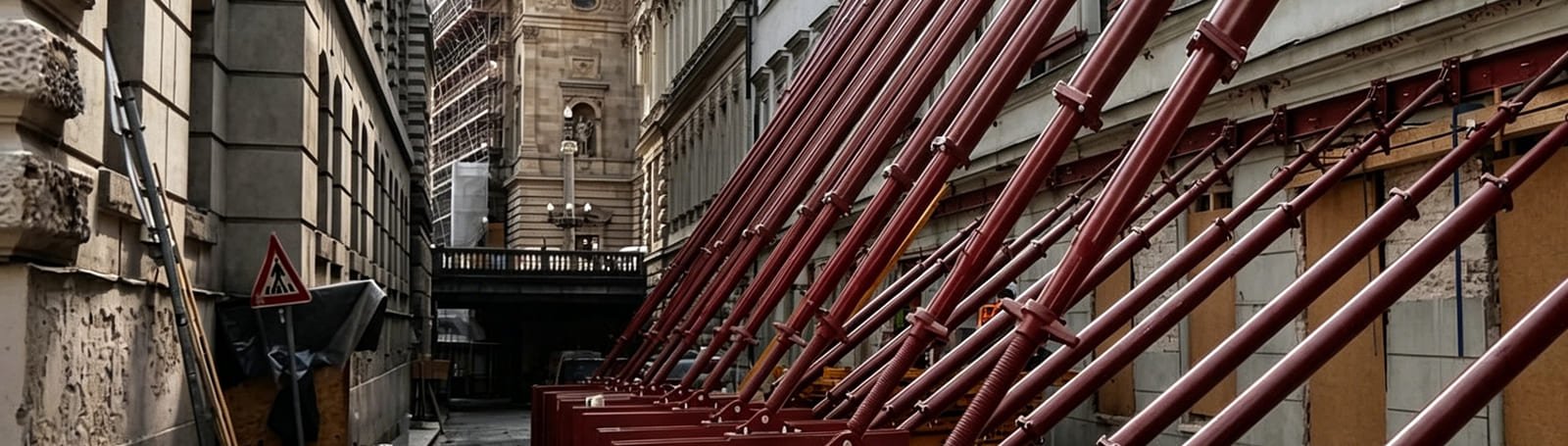
Push‑Pull Shore is a specialized adjustable steel acrow prop designed to provide lateral or inclined support against horizontal forces or sloped structures.
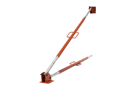
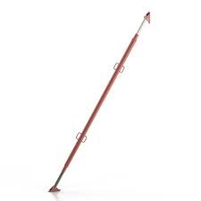
Classified by adjustment method:adjustable Push-Pull Shore is mainly divided into 2 commonly used types.
G Pin Type Adjustable Push-Pull Shore Screw-type Adjustment Push-Pull Shore
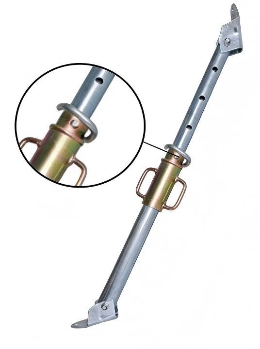
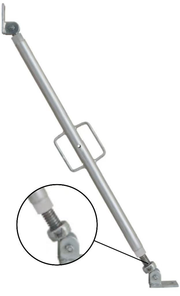
2. Adjustable Push-Pull Shore Standard Size
Tube Diameter 1
| Min Height | Max Height | Inner Tube | Outer Tube | Tube Thickness |
| 1.6m | 2.9m | 48mm | 60mm | 1.6-4.0mm |
| 1.8m | 3.2m | 48mm | 60mm | 1.6-4.0mm |
| 2.0m | 3.5m | 48mm | 60mm | 1.6-4.0mm |
| 2.0m | 3.6m | 48mm | 60mm | 1.6-4.0mm |
| 2.2m | 4.0m | 48mm | 60mm | 1.6-4.0mm |
| 3.0m | 5.0m | 48mm | 60mm | 1.6-4.0mm |
| 3.5m | 6.0m | 48mm | 60mm | 1.6-4.0mm |
| Surface Treatment | Painted/Pre-galvanized/Powder Coated/Hot-dip Galvanized | |||
| Other Specifications Can Be customized Upon Request | ||||
Tube Diameter 2
| Min Height | Max Height | Inner Tube | Outer Tube | Tube Thickness |
| 1.6m | 2.9m | 48mm | 56mm | 1.6-4.0mm |
| 1.8m | 3.2m | 48mm | 56mm | 1.6-4.0mm |
| 2.0m | 3.5m | 48mm | 56mm | 1.6-4.0mm |
| 2.0m | 3.6m | 48mm | 56mm | 1.6-4.0mm |
| 2.2m | 4.0m | 48mm | 56mm | 1.6-4.0mm |
| 3.0m | 5.0m | 48mm | 56mm | 1.6-4.0mm |
| 3.5m | 6.0m | 48mm | 56mm | 1.6-4.0mm |
| Surface Treatment | Painted/Pre-galvanized/Powder Coated/Hot-dip Galvanized | |||
| Other Specifications Can Be Customized Upon Request | ||||
Tube Diameter 3
| Min Height | Max Height | Inner Tube | Outer Tube | Tube Thickness |
| 1.6m | 2.9m | 40mm | 48mm | 1.6-4.0mm |
| 1.8m | 3.2m | 40mm | 48mm | 1.6-4.0mm |
| 2.0m | 3.5m | 40mm | 48mm | 1.6-4.0mm |
| 2.0m | 3.6m | 40mm | 48mm | 1.6-4.0mm |
| 2.2m | 4.0m | 40mm | 48mm | 1.6-4.0mm |
| 3.0m | 5.0m | 40mm | 48mm | 1.6-4.0mm |
| 3.5m | 6.0m | 40mm | 48mm | 1.6-4.0mm |
| Surface Treatment | Painted/Pre-galvanized/Powder Coated/Hot-dip Galvanized | |||
| Other Specifications Can Be Customized Upon Request | ||||
3.Advantages of Push-Pull Shore
Two-Way Active Support
Provides both push and pull preset support forces, enabling precise and active control of deformation in excavation or tunnel sidewalls.
Efficient and Flexible Installation
Modular design allows for quick assembly and length adjustment to suit varying spans and site conditions, saving construction time.
High Load Capacity and Rigidity
Utilizes hydraulic systems and high-strength steel components for excellent load-bearing performance, effectively restraining structural displacement.
Safe and Controllable
Features real-time pressure monitoring and adjustment, with visible and adjustable support forces, significantly enhancing engineering safety and reliability.
Strong Reusability
Durable design combined with standard connection methods facilitates disassembly and reuse, making it suitable for multi-phase or multiple projects with high cost-effectiveness.
4.Assembly Video of Push-Pull Shore
This video will visually demonstrate the quick assembly steps of the Push-Pull Shore, helping you complete on-site installation safely and efficiently.
5.Application Scenarios of Push-Pull Shore
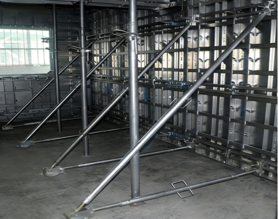
Support for Deep Excavations
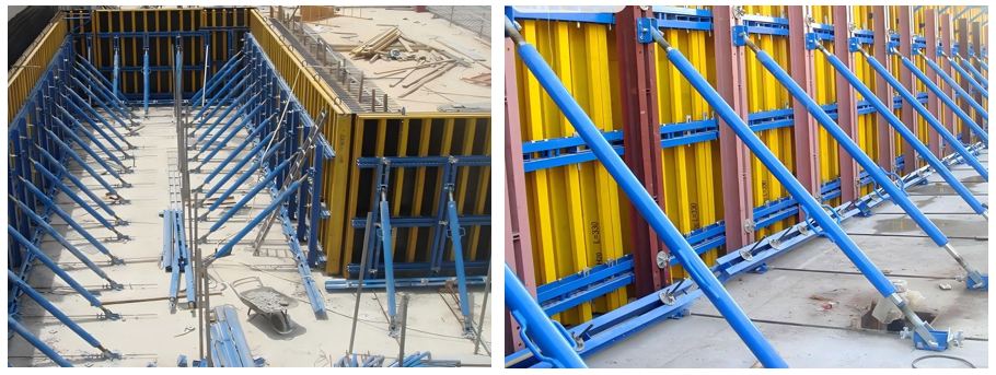
Suitable for lateral support in deep foundation pits of building basements, subway stations, underground utility tunnels, etc., particularly critical in urban dense areas, near sensitive structures, or weak soil conditions where deformation control is essential.
Support for Tunnel and Roadway Construction
Used in temporary horizontal bracing systems for tunnel excavation, mining roadways, and shield launching/receiving shafts, effectively resisting surrounding rock pressure and controlling convergence deformation to ensure construction safety.
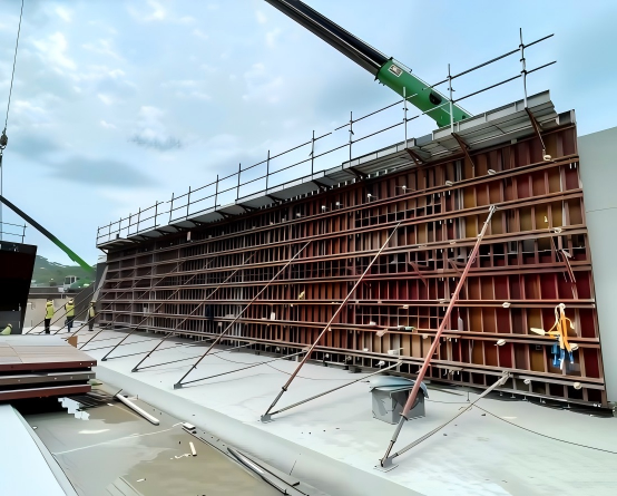
Reinforcement in ComplexStructural Conditions
Covers support for irregular or large-span foundation pits such as bridge pier excavations, hydraulic gate chambers, and industrial equipment foundations, and is also applicable to emergency scenarios like rescue reinforcement and temporary propping of existing structures.
Support for Slope Stabilization and Retaining Structures
Provides lateral reinforcement for temporary or permanent earth-retaining walls, steep slopes, and embankments. Often used in conjunction with sheet piles or soldier piles to prevent soil collapse during excavation or in landslide-prone areas.
6.Packing & Delivery
Our push-pull shore are packed in purpose‑designed steel‑frame crates or strapped bundles, with protective separators to prevent contact damage.
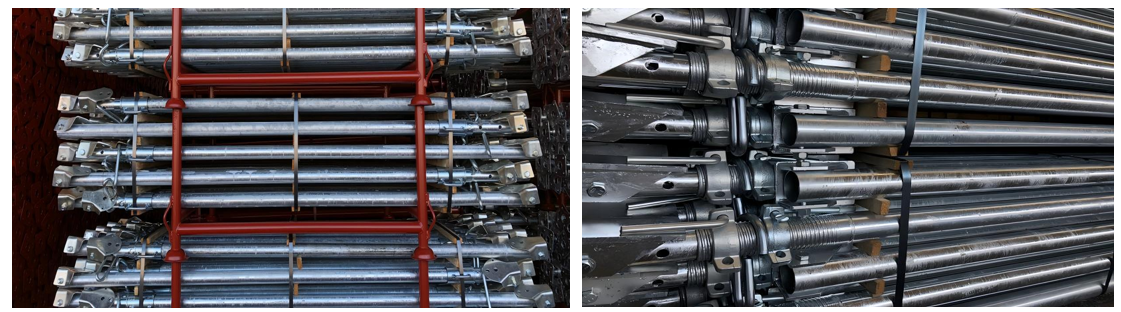
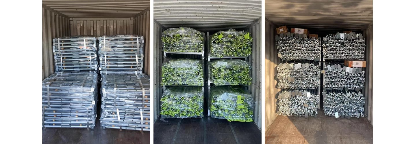
Our push-pull shore are systematically packed in steel-framed crates or strapped bundles designed to fit efficiently into standard shipping containers.
Each unit is separated with protective spacers to maintain alignment and prevent deformation during transit.
7.Certification
8.Exhibitions and Customers
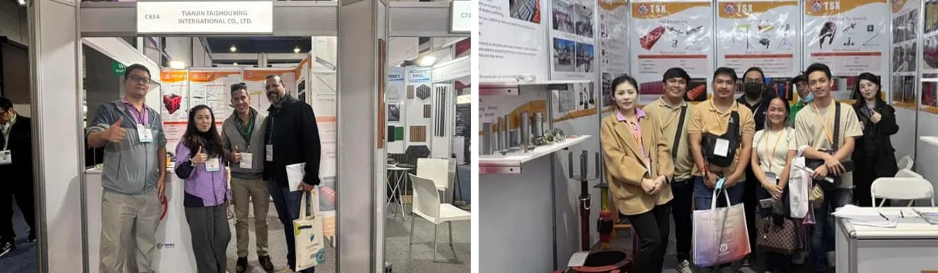
Find Us at Global Trade Shows – Let’s Build Solutions Together
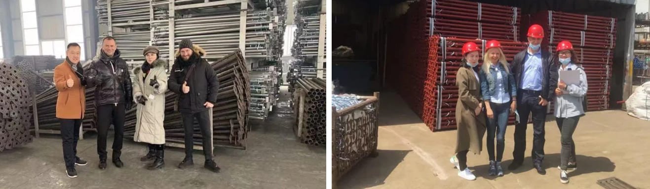
We welcome clients from around the world to visit our production facility and witness firsthand how we craft our steel prop systems and formwork solutions. From material inspection to final testing, every step is designed to deliver products that meet the highest standards of safety, durability, and performance.
FAQ
Q1: Are Push–Pull Shores Adjustable In Length And Angle?
A1:Yes. Our Push‑Pull Shores feature telescopic steel tubes with pin‑hole or screw‑type adjustment for length.It is also equipped with end connectors that allow for angle adjustment on site.
This design enables quick setup for various bracing angles (usually between 30°– 60° from horizontal) and flexible adaptation to different site layouts, ensuring efficient and secure lateral support.
Q2:How to choose the right Push-Pull Shore specifications for your project?
A2:The selection of specifications is mainly based on three core parameters:
Design Load: What is the maximum lateral force that needs to be supported (usually in kilonewtons, kN). This is the primary basis for selecting the support’s load-bearing capacity.
Support Length: Calculate the required installation length of the support based on the actual horizontal and vertical distances at the site.
Connection Ends: Choose the appropriate end fittings based on the conditions of the surface being supported:
Turnbuckle/Swivel Head: Suitable for situations where angle adjustments are needed or the contact surface is uneven.
U-shaped Head/Fork Head: Used for fixing and supporting beams or pipes.
Flat Base Plate: Used for supporting flat concrete or steel structures.
Recommendation: Provide your project drawings or site photos, and our technical team can recommend the most economical and safe specifications for your project.
Q3:What Are The Typical Applications Of Push-Pull Shores?
A3:Push‑Pull Shores are widely used for temporary lateral bracing in:
Deep excavation pits (e.g., basements, subway stations).
Tunnel excavation and shield launching shafts.
Retaining wall support during slope stabilization.
Emergency shoring for damaged or overloaded structures.
Q4: What Safety Standards Do Your Push–Pull Shores Comply With?
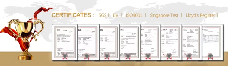
A4:Our products are designed and tested in accordance with international standards, including EN 1065 (Europe), AS/NZS 1576 (Australia/New Zealand), and BS 4074 (UK). Load capacity markings and inspection certificates are provided upon request.
Q5:What Is The Maximum Load Capacity Of Your Push‑Pull Shores?
A5:Standard capacities range from 10 kN to 50 kN, with custom high‑capacity models (up to 100 kN) available for heavy‑duty projects. Always select a shore with a rated load exceeding your design requirement by a safety factor (typically 1.5–2.0).
Q6:How Do I Install And Dismantle A Push‑Pull Shore Safely?
A6:Ensure both ends are securely connected to stable structures.
Extend the telescopic tube to the required length and lock with pins/screws.
Use a spirit level to check alignment; avoid eccentric loading.
During dismantling, release load gradually and store components clean and dry.
Q7:Can Push–Pull Shores Be Used In Corrosive Environments (E.G., Coastal Sites)?
A7:Yes. We offer hot‑dip galvanized (≥85µm coating) or painted finishes for enhanced corrosion resistance. Regular inspection and cleaning after exposure to saltwater or chemicals are recommended.
Q8:What Is The Lead Time For Custom‑Length Or Non–Standard End Fittings?
A8:Standard products: 10–15 days after order confirmation.
Customized items (special lengths/finishes/fittings): 20–30 days, depending on complexity.
Q9:Do You Provide Technical Support Or On–Site Training?
A9:Yes. We offer:
Free technical consultation based on your project drawings.
Illustrated installation manuals and multilingual safety labels.
On‑site training services for large‑scale projects.
Q10:What Is Your Warranty And After‑Sales Policy?
A10:We provide a 12‑month warranty against manufacturing defects.
Lifetime technical support and spare parts supply are available. Damage due to improper use is not covered, but we assist with maintenance guidance.
